
LA8OKA's Corned Fed Delta Loop

An example of the Corner Fed Delta Loop antenna made for 20 m.
The Delta Loop antenna is one of the famous ”magical antennas”, but in reality, the Delta Loop antenna is not as magical as it’s reputation. Despite its reputation as a Multi band antenna, it is a single band antenna. It can be somewhat tricky to make a Delta Loop with a low SWR. But after a lot of experimentation I finally found a ratio between the lengths of the sides of the Delta Loop that give reasonably low SWR into a 50 Ω coaxial cable almost independent of the high above ground and other surroundings. This ratio also gives good results no matter orientation, but the antenna have most gain when Side A is vertical and Side B is horizontal. (See the drawing above.)
The relationship between the sides
are as follows:
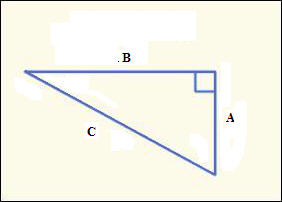
C2 = A2 + B2
A
≈ 0,3583 * (300/f[MHz])
B
≈ 0,2655 * (300/f[MHz])
C ≈ 0,4463 * (300/f[MHz])
Please note: The formulas given above are not accurate, some cutting and trying may be needed.
This Delta Loop is fed in the corner between Side A and Side C and can be fed directly with a 50 Ω coaxial cable, but I recommend that you use a 1:1 balun.
Because of the independence of its surroundings the Corner Fed Delta Loop is an excellent antenna choice for portable and Field Day operation.
Important properties of the Corner Fed Delta Loop antenna:
-
Thicker wire will give higher resonance frequency and thinner wire will give lower resonance frequency.
-
Higher height above ground will give somewhat higher resonance frequency and lower height above ground will give somewhat lower resonance frequency. (This is not a big issue.)
· It is important to keep the ratio between the Sides. The angle between Side A and Side B must be 90 degrees.
· When you have succeeded in building your own Corner Fed Delta Loop and tuned it for low SWR, the SWR will remain low in almost all surroundings as long as you keep the ratio’s and angles fixed. (The simplest way to keep the angles fixed is to keep the angle between Side A and Side B at 90 degrees, and keep the lengths of Side A and B fixed.)
Below is an online calculator which will calculate the lengths of the sides of the Corner Fed Delta Loop antenna with the correct ratio between the sides of the antenna.
The only thing you have to do is to enter the operating frequency of your choice, the diameter of your wire in millimeter and push “ENTER”, and the lengths of the sides will pop up automatically.
The lengths will be correct for an antenna made for the 20 m band. On higher bands, the resonance frequency will be slightly higher than the design frequency , and on lower bands, the resonance frequency will be slightly lower than the design frequency .
EZNEC Files:
If you want to make your own simulations using EZNEC, you can download my EZNEC files here:
LA8OKA’s Vertical Corner Fed Delta Loop
LA8OKA’s Horizontal Corner Fed Delta Loop
Please note: I had to rename the file extension to .txt because most web browser didn't recognize .EZ. Remember to rename the file extension to .EZ before you load it into EZNEC.
The EZNEC files are made for the demo version of EZNEC v 3.0 who is limited to 20 segments, if you have the full version of EZNEC, I highly recommend you to add more segments to make the simulation better.
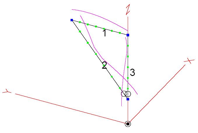
The current distribution on the Corner Fed Delta Loop antenna.
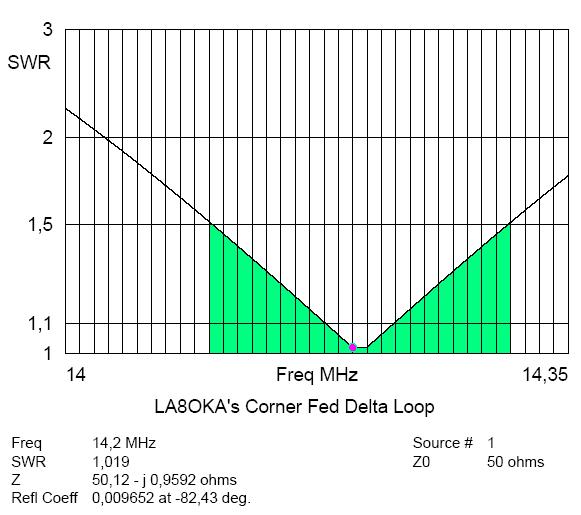
The SWR for the Vertical Corner Fed Delta Loop antenna made for 20 m.
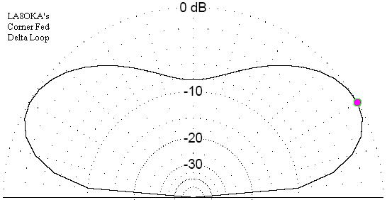
The Far Field Elevation pattern for the Vertical Corner Fed Delta Loop
antenna made for 20 m.
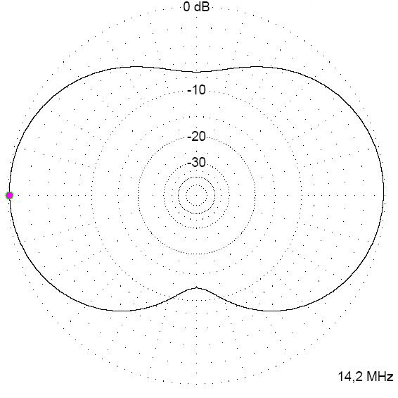
The Far Field Azimuth pattern for the Vertical Corner Fed Delta Loop antenna
made for 20 m.
This page was last updated 21.12.14 .